Moment Vs Shear Diagram
46+ Moment Vs Shear Diagram Pictures. Shear and bending moment diagrams are analytical tools used in conjunction with structural analysis to help perform structural design by determining the value of shear force and bending moment at a given point of a structural element such as a beam. Bending moment refers to the internal moment that causes something to bend.
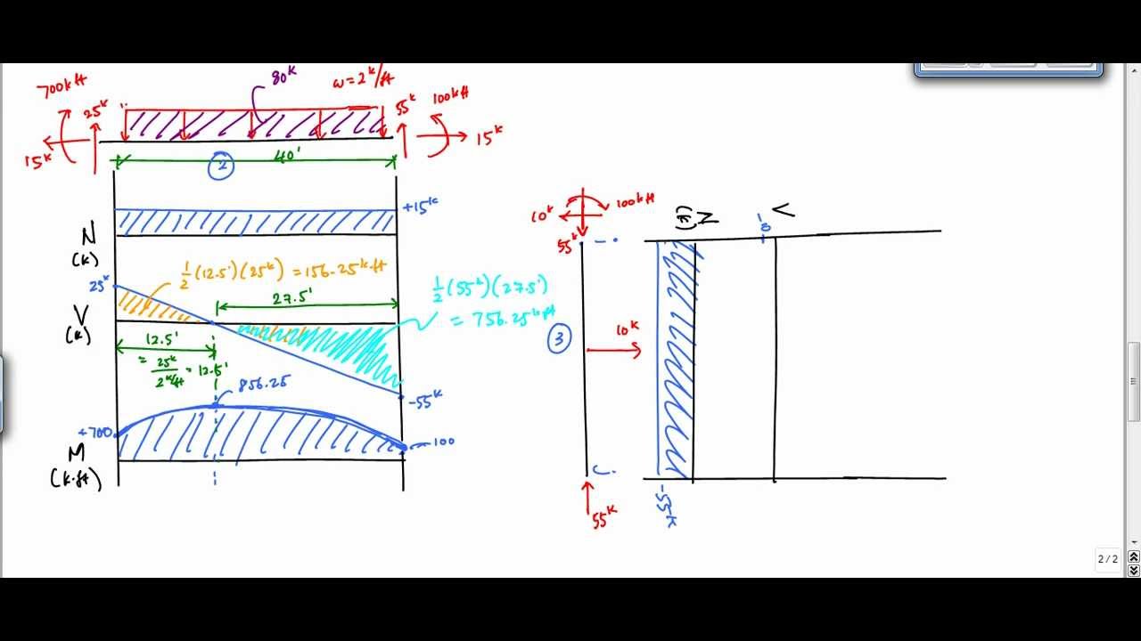
Shear and moment diagrams consider a simple beam shown of length l that carries a uniform load of w (n/m) throughout its length and is held in equilibrium by reactions r1 and also, draw shear and moment diagrams, specifying values at all change of loading positions and at points of zero shear.
This is a detailed example of shear and moment diagrams, i recommend skipping around to the sections shown below if you already have a feel for the subject. Let us draw the bending moment diagram from the shear force diagram, keeping in mind the fact that the slope of bending. This is a detailed example of shear and moment diagrams, i recommend skipping around to the sections shown below if you already have a feel for the subject. Constructing shear and moment diagrams areas and centroids.

0 Response to "Moment Vs Shear Diagram"
Post a Comment