27+ Concentric Potentiometer Wiring Diagram Images. The basic potentiometer working principle is based on the fact that the potential across any piece of the wire is directly proportional to the length of. Potentiometer circuit diagram, connection diagram.
The Potentiometer And Wiring Guide - Build Electronic Circuits from www.build-electronic-circuits.com A potentiometer is a handy little component often used to control the volume of music equipment, brightness of a light, and more. Thus, throughout the wire, it has uniform resistance. The middle and bottom pin are.
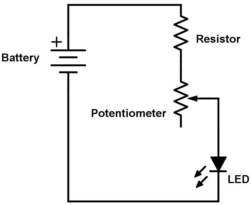
By turning the shaft of the potentiometer, we change the amount of resistence on either side of the wiper which is connected to the center pin of the potentiometer.
A potentiometer will have 3 pins, the two outer pins will connect to 5v and ground and the center pin will connect to an analog input. A quick video on how to wire a potentiometer to vary voltage for your project needs. The potentiometer consists of l which is a long resistive wire and a battery of known emf v whose voltage is known as driver cell voltage. Assume a primary circuit arrangement by connecting the two ends of l to the battery terminals.
Share this post
0 Response to "Concentric Potentiometer Wiring Diagram"

0 Response to "Concentric Potentiometer Wiring Diagram"
Post a Comment